

A Machinist’s Guide to Solving Chatter, Vibration, Wear, and Setup Problems
For CNC Machining Centers
Introduction to Angle Heads
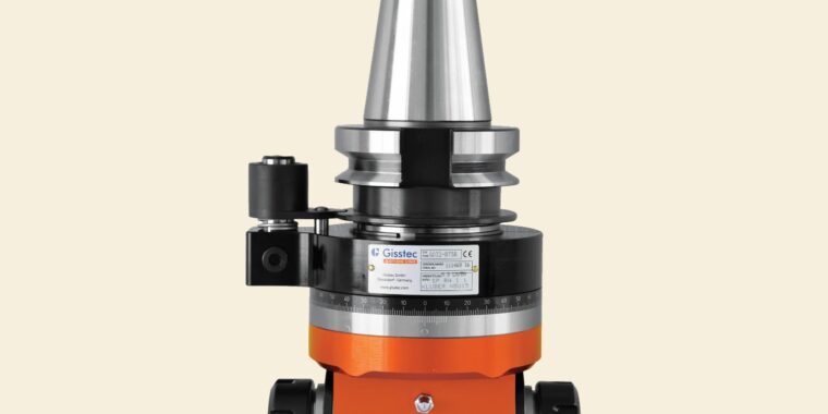
A 90° angle head turns a standard 3-axis -and in some cases 4-axis and 5-axis- vertical machining center, into something considerably more capable. By redirecting the spindle output to a perpendicular axis, it allows horizontal milling, drilling, tapping, and thread milling without repositioning the workpiece. The practical result is fewer setups, tighter feature-to-feature tolerances, and shorter cycle times on parts that would otherwise require a horizontal machining center or a secondary operation on a fixture plate.
But an angle head is not a simple adapter. It is a compact gearbox, with its own bearings, lubrication, and thermal behavior, mounted at the end of your spindle. Cutting forces that would normally travel straight up through the spindle column are now applied at a 90° angle, which means the mechanical leverage on the head’s internal components is significantly higher than what you’d see in a conventional setup. This changes the way you need to think about speeds, feeds, tool length, and workholding rigidity.
When things go wrong with an angle head, the symptoms tend to compound quickly. Chatter leads to poor surface finish, which leads to more aggressive corrections, which leads to premature gear and bearing wear. By the time the head starts making noise on its own, you’re already looking at a rebuild or a replacement.
This guide covers the most common problems machinists run into with right-angle attachments, along with the underlying mechanics of each issue and the corrective steps that tend to work in practice. It also addresses the situations where an angle head is the wrong tool for the job, because knowing when to set it aside is just as valuable as knowing how to run it.
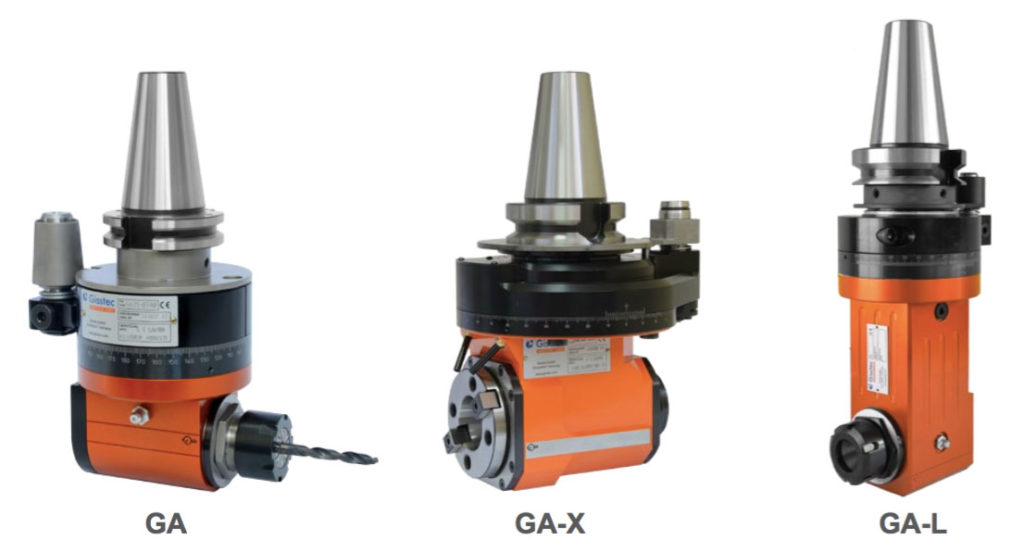
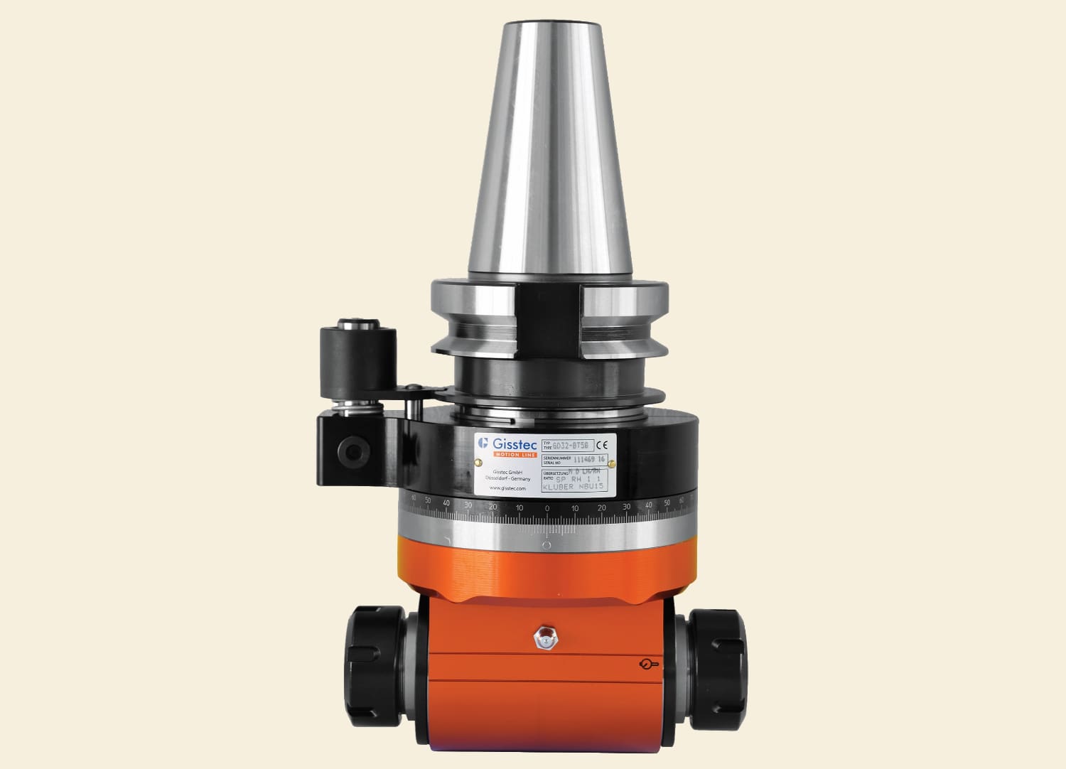
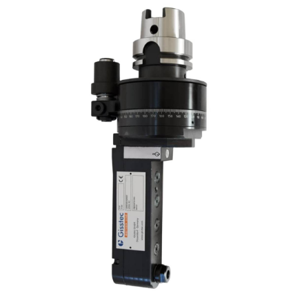
Different types of 90º Angle Heads
1. Chatter and Surface Finish Degradation
Chatter is the single most common complaint with angle heads, and it behaves differently here than it does with a standard end mill holder. In a typical vertical milling operation, the cutting force is absorbed more or less directly along the spindle axis, which is the stiffest direction of the machine. With an angle head, that force is redirected 90°, creating a bending moment on the head’s housing and a torsional load on the gear train. The result is a system that’s inherently more prone to deflection than the same tool would be if it were mounted directly in the spindle.
Chatter in machining is a form of self-excited vibration. A slight oscillation in the cutting tool produces a wavy surface on the workpiece. On the next revolution or pass, the tool encounters those waves, which modulate the cutting force, which amplifies the vibration. This regenerative feedback loop is what causes chatter to escalate from a faint squeak to a full-blown screech in a matter of seconds. In an angle head setup, the additional compliance of the gear housing and the offset tool position lower the threshold at which this feedback loop kicks in.
Excessive Tool Overhang
The most straightforward cause of chatter in an angle head is too much tool stickout. Every additional millimeter of unsupported tool length increases the deflection under load. In a conventional holder, you can sometimes get away with longer tools because the spindle bearing support is directly behind them. In an angle head, the tool is already cantilevered past the head’s output bearings, and any extra length amplifies that cantilever effect.
Use the shortest possible cutter that can reach the feature. If the job calls for depth and you’re running into chatter, consider whether you can take a shallower axial depth per pass and step down incrementally. A stub-length endmill in an angle head will almost always outperform a standard-length tool in terms of both surface finish and tool life, even if the cycle time increases slightly.
Stop Block and Orientation Pin Problems
The stop block is what prevents the angle head’s body from rotating when the spindle applies torque to the input shaft. The orientation pin on the head engages with the stop block, which is typically bolted to the spindle housing or column. If the fit between the pin and the stop block slot has any play, the head can micro-rotate during cutting. This intermittent slippage introduces a low-frequency vibration that shows up as chatter marks on the workpiece surface.
Check the orientation pin for wear. On heavily used angle heads, the pin can develop a flat spot from repeated engagement under load. Inspect the stop block slot for the same kind of wear. The pin should seat with firm hand pressure and have zero perceptible radial play. If you’re getting chatter that doesn’t respond to speed, feed, or tool length changes, the stop block interface is a good place to look.
Cutting Strategy Adjustments
If the setup is solid and the tool is short, the next lever you have is the cutting parameters themselves. Reducing the feed rate by 15–20% while maintaining the same spindle speed can move the cutting dynamics out of a resonant zone. You can also try small changes to the spindle RPM, sometimes as little as 50-100 RPM in either direction can break a chatter harmonic.
Another approach worth trying is to switch from conventional milling to climb milling, or vice versa. The direction of the cutting force relative to the tool’s deflection changes with the milling mode, and one will almost always produce less chatter than the other in a given setup. If you’re doing adaptive or trochoidal toolpaths, the constantly varying radial engagement can also help prevent the stable oscillation pattern that regenerative chatter depends on.
For end mills specifically, variable-helix or variable-pitch designs disrupt the even spacing of the cutting edges, which makes it harder for a single chatter frequency to establish itself. These tools cost more, but in angle head work where you’re already fighting the compliance of the system, they can make a noticeable difference.
2. Vibration and Internal Heat Buildup
Chatter is a cutting-related vibration, it happens because of the interaction between the tool and the workpiece. But angle heads can also vibrate on their own, without a tool in the cut, if there’s something wrong with the head itself. A high-pitched whine during free-running, a housing that gets hot after only a few minutes of use, or a noticeable increase in noise compared to when the head was new are all signs of internal friction problems.
Exceeding the RPM Rating
Every angle head has a maximum rated speed, and the range varies widely depending on the head’s design and intended application. Compact ER16 heads for light drilling might be rated to 8,000 or even 12,000 RPM. Heavier ER25 or ER32 heads built for milling are often limited to 3,000–6,000 RPM. Running a head above its rating causes problems that build on each other: the lubricant heats up and loses viscosity, the gears expand thermally and the mesh tolerance tightens, friction increases, and the heat climbs further. If this continues, the lubricant can break down entirely and the gears can seize.
Always verify the RPM rating stamped on the head or listed in the manufacturer’s documentation before writing a program. If you need higher spindle speeds for small-diameter tooling, you want an angle head that’s rated for higher RPMs. That may be a better option than pushing the angle head past its limits.
One big gotcha is with angle heads with a transmission ratio. If an angle head has a transmission ratio of 1:2 and max output RPM is rated at 6,000 RPM, and you run the machine spindle at 6,000 RPM, you get 12,000 RPM at the output of the angle head. The bearings on that head won’t last a long time.
Duty Cycle and Continuous Operation
Most mechanical angle heads are designed for intermittent duty. They work well for drilling a pattern of holes, tapping, or milling a keyway, operations that last seconds to a few minutes each, with pauses in between for tool changes or rapid moves. Running an angle head at high speed for twenty continuous minutes of slotting is a different demand altogether, and many heads are not built for it.
The issue is heat dissipation. The head’s housing acts as a heat sink, absorbing the thermal energy generated by gear mesh friction and bearing drag. Given enough time between cuts, the housing radiates that heat away. In continuous operation, the heat accumulates faster than it can dissipate, and the internal temperature climbs.
For extended operations, look into angle heads with through-coolant capability or oil-mist lubrication, which actively remove heat from the gear area during the cut. These are more expensive, but they’re built for the kind of sustained duty that a grease-packed head can’t handle.
Diagnosing Internal Bearing Issues
If the head is running within its RPM rating and the duty cycle is reasonable, but it’s still running hot or noisy, the bearings themselves may be worn. Angular contact bearings, which are typical in quality angle heads, have a preload that’s set at the factory. As the bearings wear, the preload changes, and the head may develop either excessive play (which causes vibration under load) or excessive preload from thermal expansion (which causes drag and heat).
Bearing wear is a maintenance issue, not something you can fix on the shop floor. Most manufacturers offer rebuild services, and the better ones will also re-grease and re-preload the bearings to factory spec. If your head has more than a few hundred hours of run time and it’s showing symptoms, a rebuild may be cheaper than trying to nurse it along.
3. Premature Gear and Bearing Wear
The gear train is the component that distinguishes an angle head from a simple right-angle bracket. Most quality heads use spiral bevel gears, ground, hardened gear sets with helical tooth profiles that allow smooth power transfer at the 90° turn. These gears are precision components, and they’re typically the most expensive part of the head to replace.
Load Limits and Material Removal
Angle heads are designed for drilling, tapping, light-to-medium milling, and finishing operations. The gear teeth in a compact angle head cannot absorb the same impact loads that a direct-drive spindle can. A heavy interrupted cut, an aggressive face mill, or a large-diameter endmill removing deep pockets will put stress on the gear teeth that exceeds their design intent. The result is accelerated wear, pitting on the tooth surfaces, and eventually a noticeable loss of cutting accuracy as the backlash in the gear train increases.
If the job requires heavy material removal on a face that’s only accessible with an angle head, then you want to go for an angle head that’s designed for heavy loads. This will usually be an angle head not with a collet chuck output like ER25 but a modular output which will take a full-on toolholder like an HSK63 end mill holder or a CAT40 shell mill holder. These heads are significantly larger and heavier than the more compact ones in order to house larger gears with higher torque.
Contamination and Seal Integrity
The second major cause of premature gear wear is contamination. Fine chips and coolant can enter the head’s housing through worn seals, past the collet area, or through the input shaft if the spindle interface isn’t clean. Once metallic particles are circulating in the lubricant, they act as a grinding compound on the gear teeth and bearing races. The damage is progressive and often invisible until the head starts making noise.
Inspect the seals regularly and replace them at the intervals specified by the manufacturer. If your machine uses high-pressure coolant (anything above 300 PSI / 20 bar), avoid directing the nozzle at the head’s seals, output bearing area, or the junction between the head body and the spindle taper. High-pressure coolant can force its way past seals that are perfectly adequate for flood coolant at low pressure. Some machinists aim the coolant at the tool tip from below or from the side, which keeps the cutting zone clean without pressurizing the seal area.
Lubrication Maintenance
Grease-packed angle heads are factory-filled and typically rated for a certain number of operating hours before they need re-lubrication. This interval varies by manufacturer, but a common range is every 200-500 hours of spindle-on time. Ignoring this schedule doesn’t produce an immediate failure, the head just gets gradually noisier and hotter as the lubricant degrades. By the time the symptoms are obvious, the gears may already be damaged.
Keep a log of angle head usage. If you’re running the head frequently, track the cumulative spindle hours and follow the manufacturer’s re-lubrication schedule. When re-greasing, use only the lubricant type specified by the manufacturer. Spiral bevel gears require a lubricant with specific anti-wear additives and a viscosity grade matched to the operating speed range. Using generic grease or the wrong viscosity can accelerate wear rather than prevent it.
4. Setup and Programming Considerations
Some angle head problems have nothing to do with the head itself, they originate in how the head is set up in the machine or how the tool path is programmed.
Tool Length Offsets and X-Axis Compensation
When an angle head is installed, the tooltip is no longer on the spindle centerline. The face of the output collet is offset from the spindle axis by the head’s body geometry. This means you need to establish a temporary work coordinate offset (typically in X) to account for the distance between the spindle centerline and the output tool’s centerline. Each different tool length in the angle head changes this offset, so it needs to be recalculated or measured for every tool.
Some shops use parametric programming to automate this: the program reads the tool length from the offset register and applies a calculated global shift in X so the tooltip ends up where it should be. This is worth the setup effort if you’re running angle head operations frequently.
Workholding Rigidity
The compliance of the angle head makes the entire cutting system more sensitive to workholding quality. A part that holds up fine under direct spindle milling may chatter or shift under angle head work, because the cutting forces are now directed differently—often horizontally, pushing the part sideways rather than straight down into the vise. If you’re experiencing chatter that you can’t trace to the tool or the head, look at the workholding. Adding a second vise stop, using softer jaws for better contact, or increasing the clamping force can sometimes eliminate an angle head chatter problem entirely.
Chip Evacuation in Enclosed Features
When milling slots, keyways, or other enclosed features with an angle head, chip evacuation becomes a bigger concern than it would be with a vertical tool. The head’s body takes up clearance in the cut zone, and chips have fewer paths to escape. Packed chips generate heat, increase cutting forces, and can re-cut into the finished surface. Air blast, through-tool coolant (if the head supports it), or simply programming a peck cycle with retract moves to clear chips can prevent these problems.
5. When an Angle Head Is the Wrong Tool
Knowing the limits of your tooling is a skill in itself. There are situations where an angle head can technically reach the feature but shouldn’t be the method you rely on.
High-Hardness Materials
Materials above roughly 45 HRC begin to push the limits of what an angle head can handle comfortably. At these hardness levels, the cutting forces climb substantially, and the thrust loads required to feed the tool into the material can exceed the rigidity of the head’s internal bearings. Above 50 HRC, most standard angle heads are not appropriate. The risk is not just poor performance, it’s sudden tool breakage inside the head, which can damage the collet, the output bearing, or the gears. For hard materials, a machine with a tilting head or a 4th/5th axis is a more appropriate solution.
Insufficient Bore Clearance
If the feature you’re machining is a bore, groove, or pocket, you need enough clearance between the angle head’s body and the walls of the feature to allow chips to escape. As a general guideline, you want at least 3-5 mm of clearance on each side between the head’s outer diameter and the nearest wall. If the head’s body is 40 mm in diameter and the bore is 42 mm, you have 1 mm per side, not enough. Chips will pack between the head and the wall, generate heat, and eventually cause a tool break or a scrapped part.
Slim-body or ultra-slim angle heads are available for tight-clearance work, especially sought-after in aerospace parts, with body diameters as small as 25–30 mm. If you’re regularly machining internal features that require angle head access, investing in a slim head for those specific operations is worth considering. In aerospace industry a slim-body angle head is indispensable to machine some features, where even the most agile machining centers won’t be able to do the job with a regular toolholder.
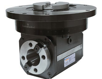
Slim Angle Head for Aerospace – GS-Series
Torque-Intensive Operations
Large-diameter face milling, heavy thread milling, and deep-hole drilling all demand sustained high torque that most angle heads can’t supply. The gear ratio in a standard angle head is typically 1:1, which means the output torque is roughly equal to the input torque from the spindle (minus friction losses). There’s no mechanical advantage being generated. If the operation requires more torque than the head’s gears can transmit, the teeth will skip, wear rapidly, or strip. Heavy-duty angle heads with conical roller bearings and oversized gear sets exist for this purpose.
6. Preventive Maintenance Summary
Angle heads are a significant investment. A well-maintained head can last years. The following schedule covers the basics.
| Interval | Action |
| Before each use | Inspect orientation pin and stop block for wear. Verify the spindle taper and head taper are clean and free of chips. Confirm the collet and tool are seated properly. |
| Weekly (or every 40 hours) | Wipe down the head body with a clean rag. Inspect seals for visible damage, cracking, or coolant leakage. Check for unusual play in the output shaft by hand. |
| Every 200–500 hours | Re-lubricate per manufacturer’s specification. Inspect gear teeth (if accessible) for pitting or uneven wear patterns. Check bearing preload by feel—the output shaft should spin freely with no perceptible radial play. |
| Annually or after 1,000 hours | Send the head for manufacturer rebuild or professional service. Replace seals, re-grease bearings, and verify gear mesh and runout to factory specifications. |
7. Pre-Cut Checklist
Run through these items before starting any angle head operation. Skipping one of them is usually how problems start.
- Is the spindle taper and the head’s input taper clean and properly seated?
- Is the orientation pin engaged in the stop block with zero radial play?
- Is the tool the shortest length that can reach the feature?
- Is the programmed RPM within the head’s rated maximum?
- Has the X-axis offset been set correctly for this tool length?
- Is there at least 3–5 mm clearance between the head body and any surrounding walls?
- Is coolant directed at the cutting zone without pressurizing the head’s seals?
- Is the workholding rigid enough to resist lateral cutting forces?
An angle head doesn’t ask for much: clean tapers, sensible speeds, short tools, and periodic maintenance. Give it those things, and it will reliably handle the kind of work that would otherwise require a second machine or a second setup. Ignore them, and you’ll spend more time troubleshooting than machining.
Resources:
https://www.skf.com/us/products/rolling-bearings/ball-bearings/angular-contact-ball-bearings
https://www.cnccookbook.com/chatter-in-machining-milling-lathe-vibration
https://ntrs.nasa.gov/api/citations/19950026758/downloads/19950026758.pdf