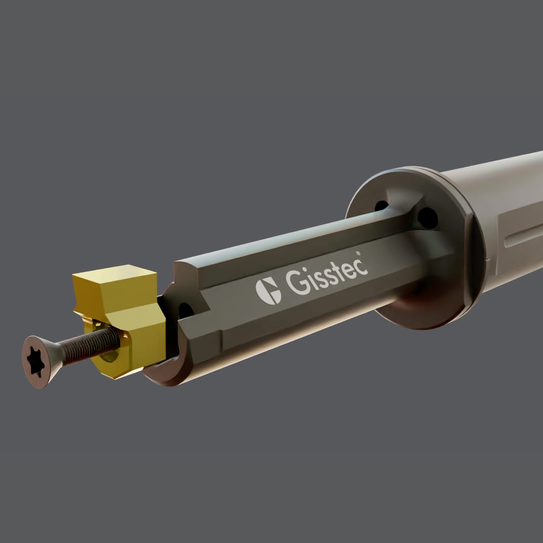
Live Broaching Units are In: Why Aerospace, Aviation, Gear-Making and Automative Industries are Switching

In industries as diverse as aerospace, aviation, machinery, automative and gear-making, the quest for high precision and efficiency never stops. From jet engine components to gear assemblies, manufacturing processes are evolving to decrease cycle times, increase automation all the while keeping to the strict quality standards.

One such development is the live broaching unit—a compact driven tool that can transform a standard lathe with a C-axis into a versatile keyway-broaching powerhouse.
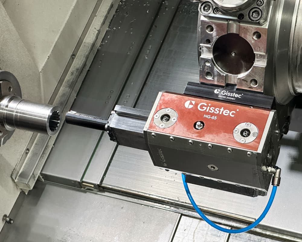
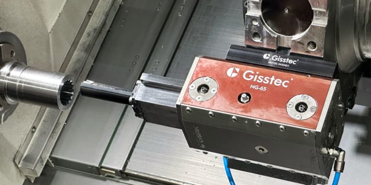
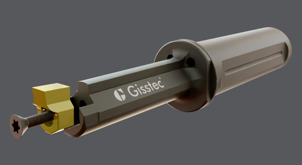
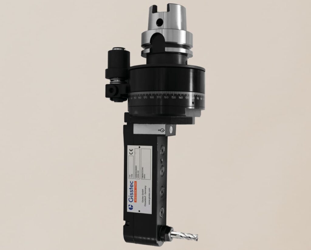
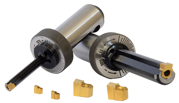
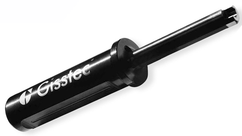
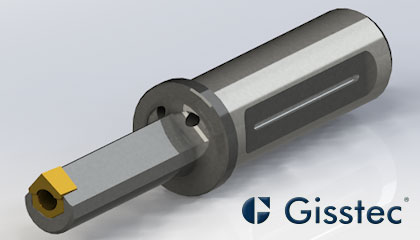
Live Broaching Unit NG-65 Gisstec, Benz ™, EWS ™, WTO ™
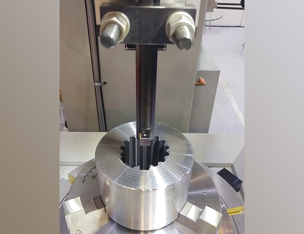
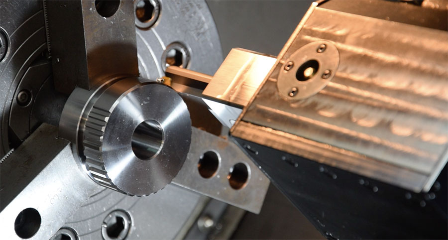
Broaching an internal spline profile with a Gisstec NG-65 Live Broaching Unit on a Lathe

If your operation regularly needs precise internal keyways or spline profiles, this broaching technology could be a pivotal addition to your manufacturing lineup.

Below, we explore how a live broaching unit stacks up against traditional broaching machines and why it’s increasingly becoming the method of choice in demanding manufacturing environments.

Quick Refresher: What Is Keyway Broaching?

Let’s start with the fundamentals. “Broaching” is a material-removal process most commonly associated with cutting keyways. A keyway is a slot, typically inside a gear or rotor, designed to accommodate a “key” that locks onto a shaft. This prevents slippage and provides the robust connection needed for transferring torque — crucial in applications like aircraft engines, power turbines, and industrial gearboxes.

The classic approach to cutting these slots involves a long, multi-tooth keyway broach. During a single pass, each successive tooth removes material until the keyway is fully formed.

Dedicated broaching machines have long been the standard for this operation—especially in high-volume manufacturing. However, they come with specific drawbacks that have spurred many organizations to seek more flexible solutions.

Some companies without a dedicated linear broaching machine or a live broaching tool use broaching services from contract manufacturers which offer tailored solutions to meet specific client needs.

Broaching Machines and Processes

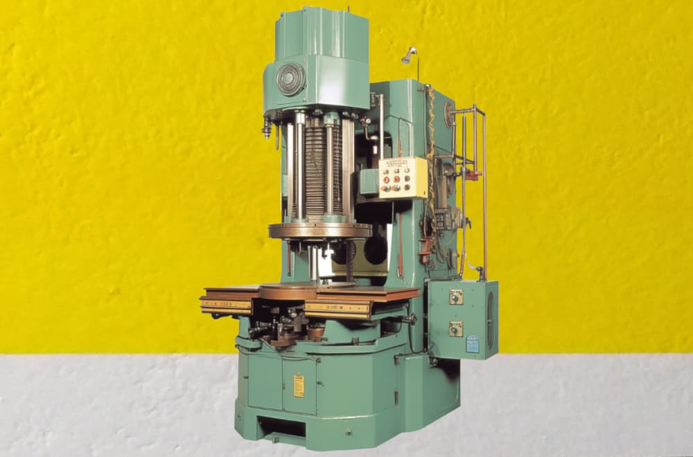
Broaching machines are specialized machine tools designed to perform the cutting process, which involves broaching precise shapes or profiles into workpieces. There are several types of broaching machines, each tailored to specific applications and varying in their mechanism of operation. The most common types include vertical and horizontal broaching machines.

Vertical broaching machines are ideal for applications requiring high precision and are often used for internal broaching tasks. On the other hand, horizontal broaching machines are designed for surface broaching and are typically used for larger workpieces that require extensive material removal.

By understanding the specific advantages and applications of each type of broaching machine, manufacturers can select the most suitable equipment for their needs, ensuring optimal efficiency and precision in their machining processes.

The Traditional Path: Dedicated Vertical Broaching Machines

Single-Purpose Operation

Conventional broaching machines are engineered with one function in mind: broaching. If your line is running large batches of identical parts a dedicated machine may still be a worthwhile choice.

But in modern manufacturing, variety is the new norm. When your product mix changes frequently or you need to produce parts of varying sizes and shapes, moving back and forth between a lathe (for turning, boring, or milling) and a separate broaching machine can become time-consuming. Each part has to be re-fixtured and realigned, introducing more opportunities for dimensional inaccuracies.

High Cost and Maintenance

Industrial broaching equipment is not just large in physical scale; it often comes with a hefty price tag and ongoing maintenance requirements.

In broaching operations, both pull and push methods are employed, each suited to specific applications.

Pull Broaching

Pull broaching, where the broach is drawn through the workpiece, is generally more prevalent, especially for internal broaching tasks. This method allows for longer broaches and is capable of handling more substantial cuts with higher precision.

Pull broaching is commonly utilized in horizontal broaching machines, which are often used for internal broaching of small to medium-sized and heavy workpieces.

Push Broaching

Push broaching involves pushing the broach through or over the workpiece. This technique is typically applied to shorter workpieces or those requiring less material removal, as push broaches are subjected to compressive loads and are made shorter in length to avoid buckling.

Push broaching is commonly used on broaching presses and is suitable for sizing holes and cutting keyways.

Specialized repairs, large-scale hydraulic or mechanical components, and the constant wear on multi-tooth broaches all factor into the total cost of ownership. And multi-tooth broaches are notoriously unforgiving—if a single tooth breaks or chips, the entire broach may need replacing.

Limited to Through Holes

An important limitation for many broaching machines is that they can typically only broach through holes. In aerospace and aviation applications especially, blind holes are often part of complex component designs.

Traditional machines that rely on pulling or pushing a broach through the entire workpiece generally aren’t equipped to handle those partial-depth requirements.
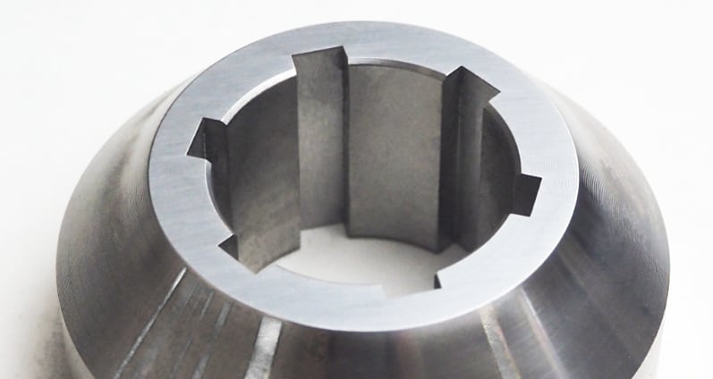
Keyway slot broach example workpiece Gisstec

The New Approach: Live Broaching Units on a Lathe

Compact and Flexible

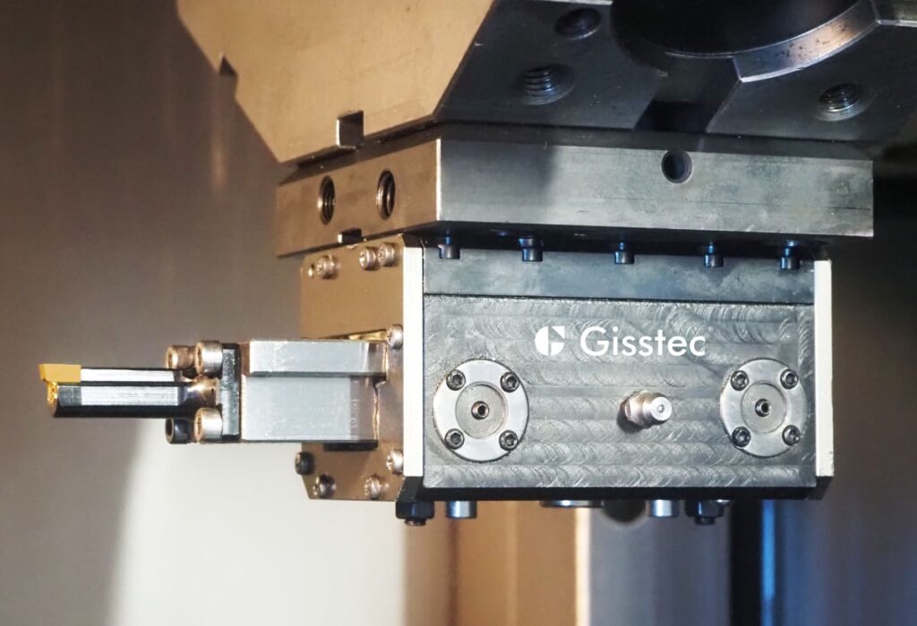
A live broaching unit is a specialized driven tool for linear broaching that mounts directly onto a CNC lathe’s turret or tool post. It’s compact, easy to mount, and doesn’t require the additional floor space of a standalone broaching machine.

This is particularly relevant in high-volume manufacturing lines where every square foot of space counts—or in advanced facilities where multiple processes must be consolidated to shorten production times.
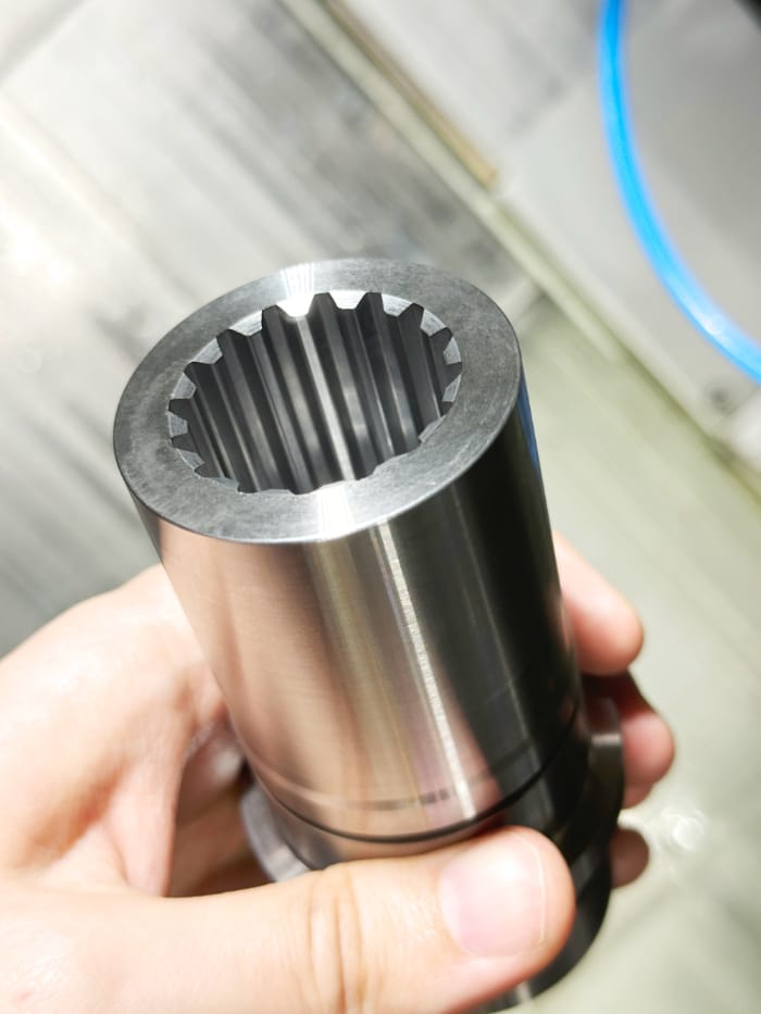
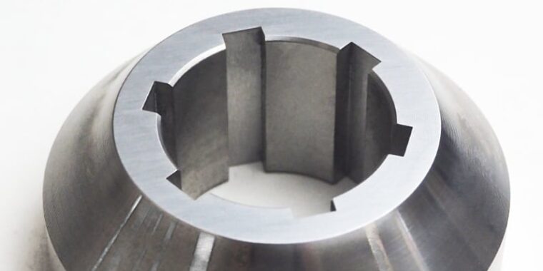
Internal spline broaching gear cutting
Internal spline profile broached with a Gisstec Live Broaching Head on a lathe

Seamless Workflow

One of the most compelling advantages is the ability to perform everything—turning, boring, drilling, and broaching—on the same machine.

This means fewer setups, reduced part handling, and minimal risk of misalignment. Whether you’re machining precision engine components for aircraft or specialized gears for heavy equipment, having all your operations in one place can significantly streamline production.

Cost-Effective Insert-Based Broaching Tools

Where traditional machines rely on large, multi-tooth broaches, live broaching units generally use single-tooth or indexable inserts.
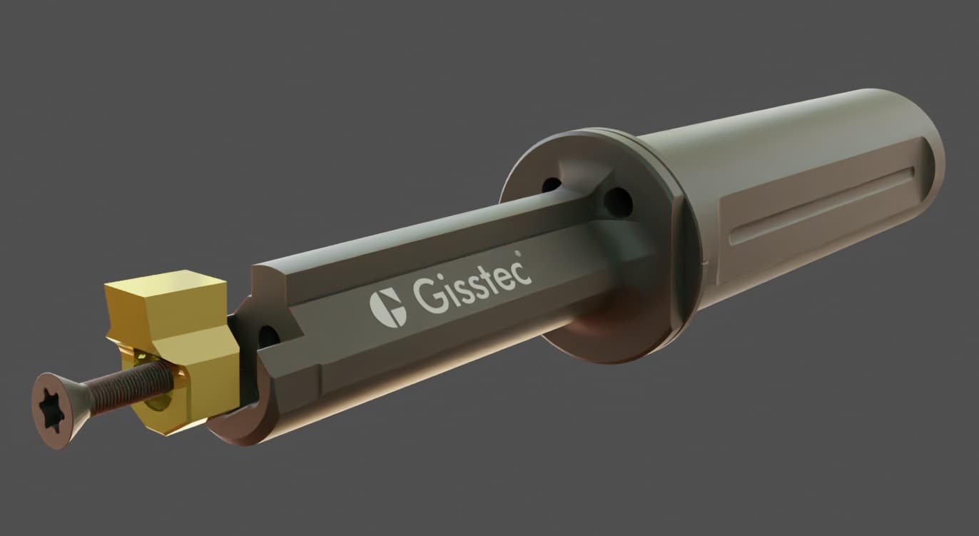
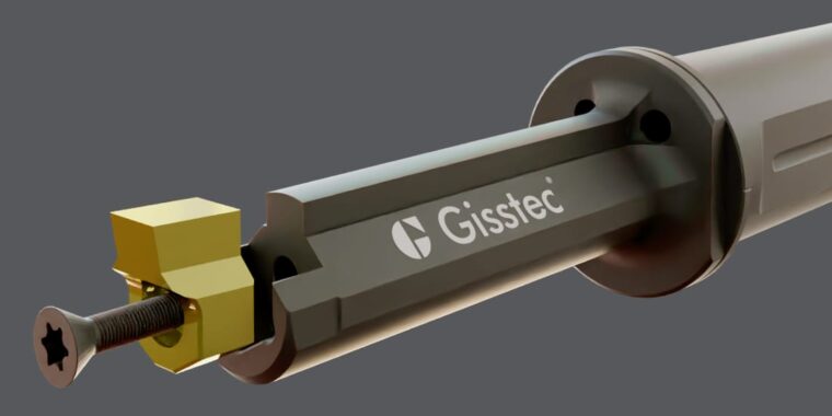
Indexable Broaching Tools Insert and Holder Gisstec, Horn ™

These inserts are economical, can be swapped out easily when worn or chipped, and allow for quick adaptation to different keyway sizes or shapes. Broach tools are versatile and have specific applications in machining processes, making them essential for achieving accurate finishes and efficient material removal across various materials like alloy steel, cast iron, aluminum, bronze.

If you’re producing diverse runs—like different gear diameters or varied aerospace components—this approach can be a major money-saver. The days of scrapping an entire multi-tooth broach because one tooth is damaged are over.

Blind Hole Capability

Unlike most dedicated broaching setups, a live broaching unit can cut keyways into blind holes. All you need is a small relief groove to allow chip evacuation at the profile’s end, and you’re set.

This opens the door for more intricate part designs common in turbines, pump systems, and rotor assemblies, where partial-depth keyways are often critical for performance.
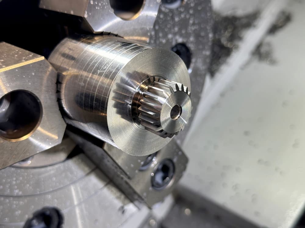
Gear Involute Spline Profile Broaching Cutting

Simplifying Complex Designs

Engineers have historically been forced to design around the constraints of through-hole machining, sometimes resulting in overly complex or hard-to-manufacture parts.

Now, with advancements such as live broaching units and improved tooling technology, designs can be approached more freely, allowing blind holes and partial length keyways and involute spline profiles to be incorporated without compromising manufacturability.

This flexibility not only simplifies the production process but also opens the door for innovative component designs that were previously impractical.

Advantages Across Industries

Faster Turnaround with Reduced Handling

Every time a part is transferred from one machine to another, there’s a chance for error or damage. In aerospace or aviation manufacturing, where tolerances can be extremely tight, minimizing re-fixturing is essential. Live broaching keeps the workpiece in the lathe chuck, ensuring consistent alignment and rapid part processing.

Lower Overall Investment

Dedicated broaching machines can command a significant upfront investment, not to mention the operating and maintenance costs.

A live broaching unit, on the other hand, is typically far less expensive and makes use of your existing equipment and infrastructure.

This more flexible setup can be appealing if you’re balancing the purchase of other specialized machinery—like 5-axis CNC mills or advanced inspection systems—needed for cutting-edge aviation or aerospace projects.

Scalable for Large or Small Batches

Some industries—such as gear-making for large-scale construction equipment—might deal with extensive production runs. Others, like custom aerospace component manufacturers, may see smaller, highly specialized batches.

Live broaching units adapt easily to both situations. When you’re producing keyways across various part sizes, simply swap out the inserts as needed. This adaptability keeps machine downtime to a minimum, allowing you to respond quickly to changing production orders.

Integrated Programming and Automation

Modern CNC lathes often come with sophisticated software that can handle complex tool paths, and integrating a broaching operation is typically a straightforward add-on.

The manufacturing process can be automated using the same G-code routines you employ for turning and milling, simplifying training and reducing the risk of human error.

In sectors where process validation and repeatability are paramount—like aerospace—this level of control can significantly improve quality assurance.

Improved Floor Space Utilization

Whether you’re building jet engines or heavy industrial gearboxes, the manufacturing floor is always at a premium. By attaching a broaching unit to your lathe, you avoid having to carve out space for a standalone broaching system.

That’s good news for sprawling factory setups where multiple production lines operate simultaneously, as well as for more constrained facilities that are constantly juggling machine placement.

How About Rotary Braoching?

Rotary broaching is a unique machining process designed to efficiently create precise internal and external profiles by simultaneously rotating both the cutting tool and the workpiece.

This technique is widely used in applications requiring polygonal shapes such as hexagon holes, square holes, or splines, often found in fasteners, gears, and other mechanical components.

How Does Rotary Broaching Work?

In rotary broaching, the cutting tool is mounted at a slight angle (typically 1°) relative to the workpiece axis. As the tool and workpiece rotate, the angled broach applies pressure to cut the desired profile.

The key to this process is the synchronized rotation of the tool and workpiece, which reduces cutting resistance and enables the broach to carve out the profile with precision and minimal stress.

Key Benefits of Rotary Broaching

  1. Efficiency: It completes the profile in a single pass, significantly reducing cycle times compared to multi-step broaching processes.
  2. Versatility: The process can be applied to a wide range of materials, including steel, aluminum, and titanium, making it suitable for industries such as aerospace, automotive, and medical devices.
  3. Compact Setup: Internal broaching and external broaching can be performed on standard CNC lathes, turning machines, machining centers or mills with the appropriate tool holders.

Limitations of Rotary Broaching

While rotary broaching offers numerous advantages, it is not without its limitations:

  • High Cutting Forces: The process requires substantial cutting forces, limiting the size and depth of the profiles that can be created. Very deep or large profiles may exceed the capacity of rotary broaching tools. That’s where live broaching tools come in.
  • Material Hardness: Extremely hard materials may pose challenges for rotary broaching, as the required cutting forces increase significantly.
  • Complex Profiles: While excellent for simple polygonal shapes, rotary broaching is not ideal for creating highly intricate or non-uniform profiles.

Applications of Rotary Broaching

Rotary broaching is a go-to process for a variety of industries and applications :

  • Fasteners: Manufacturing hexagonal, square or torx sockets for bolts, screws, and other fasteners.
  • Gears and Splines: Producing internal splines or other profiles used in power transmission components.
  • Medical Devices: Machining precise internal features in surgical instruments and implants.

Important Considerations Before Making the Switch

Lathe Requirements

Not all lathes are created equal. Your lathe needs to be rigid enough and have sufficient horsepower to handle the forces generated during broaching—especially for larger or tougher materials frequently used in aerospace (think titanium or high-strength steel).

Always consult the manufacturer’s recommended guidelines for spindle power, tool pressure, and cutting speeds.
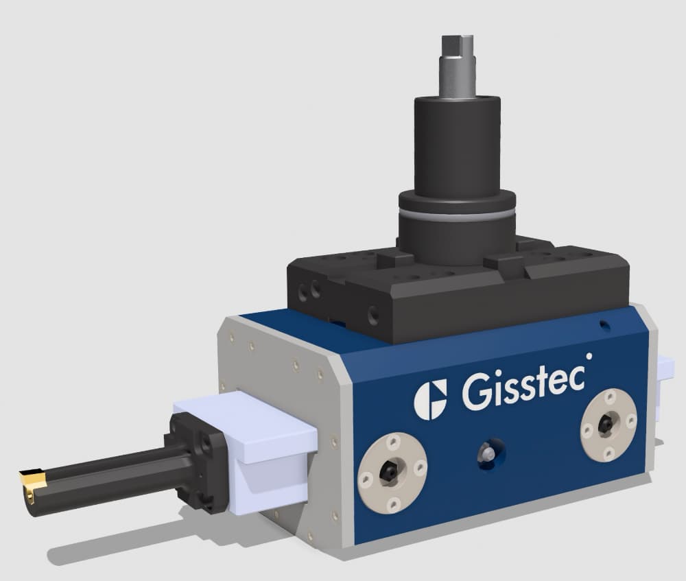
Live Broaching Tool Gisstec Slotting Keyway Cutting
Gisstec Live Broaching Unit

Monitoring Tool Wear

Broaching, like any machining operation, puts stress on cutting edges. If you’re working with exotic aerospace alloys or hardened gear steels, tool wear can accelerate. Regular inspection and routine insert changes will help maintain quality.

Adhering to recommended speeds, feeds, and lubrication protocols also prolongs tool life.

Safety and Training

Proper training is non-negotiable. While attaching and using a live broaching unit isn’t overly complex, it does require a solid understanding of both lathe operations and broaching fundamentals.

Employees should be aware of clearance settings, proper clamping procedures, and safety measures like protective eyewear and guarding.

Conclusion

From aerospace engine shafts to massive gears in heavy machinery, keyways are integral to ensuring reliable power transmission. While traditional broaching machines have served this purpose for decades, the rise of live broaching units is reshaping how companies approach the task.

They’re flexible, cost-effective, and efficient, making it easier than ever to integrate keyway broaching right on the production floor—no additional machine required.

If your organization is grappling with tight deadlines, space constraints, or a diverse product mix, consider a live broaching unit. You’ll save on tooling, speed up production, and open the door to new design possibilities such as blind hole keyways.
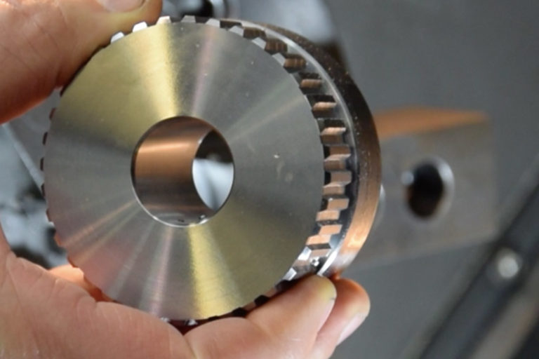
Spline-Broaching-Slotting-Sample-Gisstec-

Dedicated broaching machines may still hold their ground in certain high-volume or specialized scenarios. But for many operations across aerospace, aviation, machinery, and gear-making, the adaptability and efficiency of live broaching can be a game-changer.

In the high-stakes world of advanced manufacturing—where efficiency, precision, and innovation converge—every competitive edge counts.

By integrating a live broaching unit into your lathe-driven workflow, you can expand your capabilities, reduce overhead, and maintain the high quality your clients demand.

Whether you’re building the next generation of jet engines or large industrial gear trains, live broaching could be the key to elevating your production processes to new heights.

FAQ

1. What is a live broaching unit?

A live broaching unit is a compact, driven tool that attaches to a lathe, transforming it into a keyway-broaching powerhouse. This attachment enables efficient cutting of keyways, involute spline profiles, and other intricate shapes directly on the lathe, eliminating the need for separate broaching machines.


2. How does a live broaching unit work?

Live broaching units use single-tooth or indexable inserts mounted on a lathe’s turret or tool post. The unit applies precise cutting forces to create keyways or splines while the workpiece is held in place. This process reduces setup time and ensures consistent results in a single machine setup.


3. What are the advantages of live broaching units compared to traditional broaching machines?

  • Space-saving: Live broaching units eliminate the need for a separate broaching machine.
  • Cost-effective tooling: They use replaceable inserts, reducing the cost of tooling compared to multi-tooth broaches.
  • Flexibility: They allow for blind hole broaching, enabling complex designs.
  • Time efficiency: Operations like turning, boring, and broaching can be performed in one setup, reducing handling and cycle times.

4. Can live broaching units handle blind holes?

Yes, live broaching units can cut keyways into blind holes. By incorporating a small relief groove at the bottom of the hole, chip evacuation is made possible, overcoming the limitations of traditional broaching machines that can only handle through holes.


5. What types of broaching processes are commonly used?

  • Pull Broaching: The broach is pulled through the workpiece, ideal for internal broaching with high precision.
  • Push Broaching: The broach is pushed through or over the workpiece, suitable for smaller cuts and shallow profiles.
  • Rotary Broaching: The tool and workpiece rotate simultaneously, perfect for creating polygonal shapes like hexagons and squares in one pass.

6. What are the limitations of traditional broaching machines?

  • They are generally limited to through holes.
  • High equipment costs and maintenance needs.
  • Limited flexibility for low-volume or highly varied production runs.
  • Multi-tooth broaches are expensive and can become unusable if a single tooth is damaged.

7. What are the key benefits of rotary broaching?

Rotary broaching is highly efficient for creating profiles such as hexagons and squares. It completes the profile in a single pass and is versatile enough for a wide range of materials, including steel, aluminum, and titanium. However, it requires substantial cutting forces and is less suitable for large or intricate profiles.


8. How do live broaching units impact manufacturing flexibility?

Live broaching units allow engineers to design freely without being constrained by the limitations of through-hole broaching. Features like blind holes and partial-depth keyways can now be incorporated without compromising manufacturability, enabling more innovative and cost-effective designs.


9. What industries benefit most from live broaching units?

Industries such as aerospace, aviation, machinery, gear-making, and medical device manufacturing benefit from live broaching units due to their ability to handle precision components efficiently while maintaining high quality.


10. What factors should be considered before using a live broaching unit?

  • Lathe capability: Ensure your lathe is rigid enough and has sufficient power for broaching.
  • Tool wear: Regularly inspect and replace inserts to maintain quality.
  • Training: Operators must understand the process and safety measures for successful implementation.

11. Why are live broaching units more cost-effective?

Live broaching units use affordable, replaceable inserts instead of expensive multi-tooth broaches. This reduces tooling costs significantly, especially for varied production runs or applications requiring frequent insert changes.


12. What are the best applications for live broaching units?

Live broaching units are ideal for:

  • Keyways in blind and through holes.
  • Internal spline profiles for gear systems.
  • Aerospace and automotive components requiring tight tolerances and complex features.

13. Can rotary broaching be performed on a standard CNC lathe?

Yes, rotary broaching can be performed on standard CNC lathes or mills equipped with the appropriate tool holders, making it a versatile option for creating polygonal shapes in fasteners, gears, and other components.


14. How do live broaching units improve production efficiency?

By combining turning, boring, and broaching in a single machine setup, live broaching units reduce part handling, minimize re-fixturing, and speed up production cycles while maintaining precision.


15. How do live broaching units simplify complex designs?

Engineers no longer need to design around through-hole constraints. Live broaching units allow for the seamless inclusion of blind holes, partial-depth keyways, and intricate profiles, making previously challenging designs more feasible to manufacture.
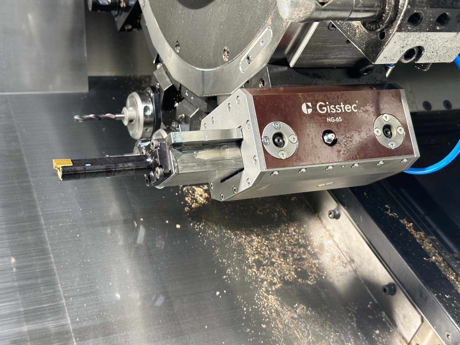
Live Broaching Unit

Keywords: Live broaching unit, driven broaching tool, push broaching, pull broaching, rotary broaching, continuous broaching


Ultimate Guide to Keyway Broaching on CNC Lathes in 2025

Introduction

Keyway broaching (keyway slotting, key slotting) is an essential machining process used to create internal slots or keyways in a workpiece, such as a gear. These keyways enable power transmission between the workpiece and a coupling component, such as a shaft.

Keyway slot broach example workpiece Gisstec

Traditionally, dedicated broaching or slotting machines have been used for keyway broaching. However, thanks to CNC (Computer Numerical Control) technology, this process can now be performed more efficiently and with greater precision on CNC machines, including lathes (turning machines) and machining centers.

This not only streamlines the process but also eliminates the need to unclamp and reclamp the workpiece.

This comprehensive guide will provide an in-depth look at the keyway broaching operation specifically broaching on a lathe, covering the following aspects:

  1. What is Keyway Broaching?
  2. Advantages of Keyway Broaching on a Lathe
  3. Tooling Selection for Keyway Broaching on Lathes
  4. CNC Lathe Setup and Programming for Keyway Broaching
  5. Best Practices for Keyway Broaching on CNC Lathes
  6. Troubleshooting Common Keyway Broaching Issues on CNC Lathes
  7. Conclusion

1. What is Keyway Broaching?

Keyway broaching is a machining process that involves removing material from a workpiece to create an internal slot or keyway, which is crucial for the transmission of torque between mechanical components, such as gears and shafts. Unlike rotary broaching, this broaching process finishes the profile with multiple passes. This allows for broaching larger profiles which is not possible with rotary broaching process.

How it has been done

This operation has been traditionally done on broaching machines using a broach, a long and slender cutting tool with a series of progressively larger teeth or cutting edges along its length.

This geometry allows the broach to gradually remove material from the workpiece as it is pulled or pushed through it until the final size of the keyway is achieved. Commercially they are purchased in a keyway broach set or as a single broach for a specific size.

How to do it now

However on CNC machines an indexable cutting tool (also referred to as insert, broaching insert, slotting insert or keyway cutter) is used, which can be replaced when worn out or chipped, eliminating the need to replace the entire tool.

The insert is first fixed to an insert holder (broaching tool, broaching holder) which is then typically clamped to a boring bar holder either on a VDI or BMT tool, depending on the machine’s turret type.

To perform the broaching operation, the workpiece is clamped on the lathe chuck or a fixture. Material is then progressively removed with each pass of the keyway broaching tool until the final keyway size is achieved.

The keyway’s desired depth is controlled by the X-axis feed, its length by the Z-axis feed, while the width of the keyway is determined by the broaching insert’s width.

Types of Broaching on CNC Lathes

This article is for static keyway broaching tools where the movement of the machine’s turret is used for the  broaching process. Static broaching tools are recommended for smaller batches.

For high-speed broaching where the movement on the Z-axis is provided by the live tool, which is recommended for larger batches and serial production, read the following article instead: Live broaching tools (also known as live broaching unit, driven broaching tool, driven broaching unit, driven broaching head)

2. Advantages of Keyway Broaching on a Lathe

Keyway broaching on CNC lathes offers several advantages over traditional broaching machines:

  1. Flexibility: Indexable inserts allow for a great flexibility with various tolerances (such as H7, JS9, P6, D10, C11) and profiles (square, hexagon, spline) at a relatively low cost.
  2. Precision and Repeatability: CNC lathes offer high levels of precision and repeatability, ensuring consistent and accurate keyway dimensions across multiple workpieces. This precision is essential for achieving the proper fit between the key and the keyway, which is critical for reliable torque transmission.
  3. Reduced Setup Time: Cutting keyways on a CNC lathe eliminates the need for dedicated broaching machines and reduces setup time.
  4. Reduced Logistics Efforts: An alternative approach is outsourcing the work to a contract manufacturer. However, this creates additional logistical efforts such as batching, labelling and shipping the parts.
  5. Cost-Effectiveness (Machine): As CNC lathes can perform multiple operations, using a single machine can save on costs associated with acquiring and maintaining dedicated broach machines.
  6. Cost-Effectiveness (Tooling): Traditional multi-tooth broaches that are used on broaching machines are relatively expensive. This makes buying and keeping multiple sizes and tolerances costly.
  7. Blind Keyways: One of the many advantages is the possibility to broach blind keyways. On a traditional broach machine it’s possible to broach only through keyways.

3. Tooling Selection for Keyway Broaching on CNC Lathes

Consider the following factors when selecting broaching tools for keyway broaching on a CNC lathe:

Broaching Slotting Tools Gisstec

  1. Insert Material: Common broach materials consist of high-speed steel (HSS) and carbide. In high-speed broaching operations, like those involving live broaching tools, carbide inserts usually result in a longer cutting tool lifespan. On the other hand, for lower-speed operations, such as with static broaching tools that operate in conjunction with turret movement, HSS alloy inserts may yield superior surface quality and tool durability.
  2. Insert Geometry: The broaching insert’s geometry should match the desired keyway dimensions, including width, depth, and profile. Standard broaching inserts are available in various sizes and tolerances for keyways, and shapes such as square, hexagon and spline profiles. Custom inserts can also be designed for unique keyway geometries and tolerances.
  3. Coating: Insert coatings can enhance the cutting performance and extend the tool life. Common coatings include Titanium Nitride (TiN) and Titanium Aluminum Nitride (TiAlN) for harder workpieces, which improve wear resistance and reduce friction between the broach and the workpiece material.
  4. Insert Holder: An insert holder is required to secure the insert in the CNC lathe’s turret. The holder is typically clamped to a boring bar holder, usually with a VDI or BMT interface depending on the machine turret. The holder should provide adequate support for the broach during the machining process.

4. CNC Lathe Setup for Keyway Broaching

Setting up a CNC lathe for keyway broaching involves the following steps:

  1. Tool Setup: Screw the broaching insert to the insert holder. Then clamp the insert holder to the appropriate boring bar holder on the CNC lathe’s turret. Ensure that the insert and the holder are securely clamped and aligned with the workpiece’s keyway location.
  2. Workpiece Setup: Clamp the workpiece on the CNC lathe, ensuring that it is properly aligned with the insert.
  3. CNC Program: Write a CNC program for the keyway cutting operation. Specify the cutting parameters, such as feed rate and depth of cut and coolant application if available.
  4. Broaching Process: The CNC lathe moves the broaching insert along the keyway length, progressively removing material with each pass. The depth of cut is incrementally increased until the desired keyway size is achieved. Unlike traditional multi-tooth broaches, the single-tooth broaching insert performs multiple passes to create the keyway.
  5. Test: Conduct a test run of the CNC program to verify a smooth keyway broaching operation, free of collisions or errors.
  6. Broaching & Finishing: Upon achieving the desired keyway dimensions on the workpiece, retract the CNC lathe turret and remove the workpiece. Inspect the keyway for accuracy and complete any necessary finishing processes.

5. Best Practices for Keyway Broaching on CNC Lathes

To achieve optimal results when using keyway broaching tools on lathes, follow these best practices:

  1. Optimize Cutting Parameters: Select appropriate cutting parameters, such as feed rate and depth of cut, based on the broach material, workpiece material, and keyway geometry. Optimizing these parameters will ensure efficient material removal and minimize tool wear.
  2. Use Appropriate Coolant: Apply coolant during the keyway cutting process to reduce heat generation, prevent tool wear, and improve surface finish. Choose a coolant that is compatible with both the workpiece and broach materials.
  3. Cutting a Keyway in a Blind Hole: To ensure effective chip removal in a blind hole, the cutting edge of the insert must pass through the full length of the keyway into a relief groove. Without proper chip evacuation, the chips can accumulate and cause issues like breakage of the insert. To avoid this, calculate the diameter and length of the relief groove based on the keyway width and depth.
  4. Ensure Proper Alignment: Ensure that the broach is properly aligned with the workpiece’s keyway location before starting the machining process. Misalignment can result in uneven keyway dimensions and excessive tool wear. If your lathe doesn’t have a Y-axis, use an eccentric bushing to correct eventual errors on the Y axis.
  5. Starting Point at Z-Axis: Start at least 10mm away from the workpiece on the Z-axis to allow for acceleration. If you start too close to the workpiece you’ll risk chipping the insert.
  6. Monitor Tool Wear: Regularly inspect the broach for signs of wear, such as chipping or dull cutting edges. Replace worn broaches promptly to maintain consistent keyway dimensions and prevent damage to the workpiece.
  7. Perform Regular Maintenance: Regularly clean and maintain the CNC lathe, broach, and tooling to ensure optimal performance and extend the service life of the equipment.

6. Troubleshooting Common Keyway Broaching Issues on CNC Lathes

When encountering issues during the keyway cutting process on CNC lathes, consider the following troubleshooting tips:

  • Inaccurate Keyway Dimensions: Check the broach geometry, CNC program, and alignment of the broach and workpiece. Make any necessary adjustments to ensure accurate keyway dimensions.
  • Excessive Tool Wear: Inspect the cutting parameters, broach material, and coolant application. Adjust these factors as needed to minimize tool wear and extend the broaching insert’s service life.
  • Poor Surface Finish: Evaluate the cutting parameters, broach geometry, and coolant application. Optimize these factors to improve the surface finish of the keyway.
  • Keyway not centered: Compensate for errors on the Y-axis. If your CNC lathe doesn’t have a Y-axis, use an appropriate eccentric bushing to correct errors on the Y axis.
  • Machine Vibrations: Check the broach holder, workpiece clamping, and machine leveling. Ensure that all components are secure and properly aligned to minimize vibrations during the machining process.

7. Conclusion

Embracing inserted keyway broaching tools on CNC lathes enables manufacturers to create internal slots and keyways with unmatched precision, efficiency, flexibility and cost-effectiveness. Additionally, the ability to complete the workpiece in a single setup offers enhanced flexibility in manufacturing. This makes it an excellent choice of tooling for manufacturing professionals to streamline their production process.

Keyway slotting on CNC lathes is optimal for a diverse range of workpieces composed of various materials from aluminium and steel to titanium.

Keyway Broaching Slotting Cutter Workpiece Gisstec

Harnessing the power of keyway broaching on CNC lathes elevates the manufacturing process, using static broaching tools for smaller batches and high-speed broaching with live broaching units for serial production.

To succeed in this, it’s important to select the right broaching tools, optimize the CNC lathe setup and programming, and follow best practices. This will enable manufacturers to achieve consistent and accurate keyway dimensions, ensuring constant high quality with reliable torque transmission between coupling components.

Contact Us for a Quote for Broaching Tools

Top 7 Internal Keyway Cutting Methods: How To Choose the Right One

Keyways play a crucial role in mechanical systems, enabling power transmission between shafts and other machine elements. Cutting an internal keyway can be a challenging task, but with the right method and tools, it can be done with precision and efficiency. 

In this comprehensive guide, we will discuss seven popular internal keyway cutting methods. We will explore the advantages and limitations of each method, provide use case examples, and offer best practices to help you make an informed decision.

7 Methods for Cutting Internal Keyways

  1. Broaching
  2. Inserted broaching tools
  3. Driven broaching heads (Live broaching tools)
  4. Shaping / Slotting
  5. Keyseating
  6. Milling
  7. Wire-Cut EDM

1. Broaching

What you need

Machine: A Broaching machine
Tooling: Keyway Broaches

Introduction

Broaching is a widely used method for cutting internal keyways, involving the use of a broach—a specialized cutting tool with a series of progressively larger teeth. The broach is clamped on the broaching machine and either pulled or pushed through the workpiece to broach the keyway.

Broaching Machine

Advantages

  • High precision and accuracy: Broaching can cut keyways with tight tolerances and excellent repeatability.
  • Surface finish: The progressive cutting action of a broach results in a smooth surface finish.
  • Suitable for high-volume production: Broaching is a fast and efficient method, making it ideal for mass production.

Limitations

  • Expensive tooling and machinery: Broaching machines and custom broaches can be costly investments.
  • No blind holes: The broach has to go through the workpiece for this method.
  • The workpiece cannot be finished on one machine and needs to be reclamped. Because only the broaching operation can be done with this method.
  • Limited to certain material types: Broaching is generally suited to softer materials and may struggle with harder or more abrasive materials.
  • Less flexible due to custom tooling requirements: Broaches are designed for specific keyway geometries, making it difficult to accommodate design changes or multiple keyway profiles.

Use case examples

  • Automotive industry: Transmission gears and components, such as synchromesh assemblies.
  • Aerospace: Turbine engine components, including compressor and turbine disks.
  • Heavy machinery: Gearboxes, shaft couplings, and power transmission components.

Best practices

  • Ensure proper alignment of the broach and workpiece: Accurate alignment is crucial to avoid tool deflection and ensure consistent internal keyway dimensions.
  • Use the correct broach size and type for the desired keyway geometry: Selecting the appropriate broach will ensure optimal cutting performance and extend tool life.
  • Regularly inspect and maintain the broaching tool to prevent wear and damage: Keeping the cutting edges sharp and free of damage will improve cutting performance and extend tool life.

2. Keyway Cutting with Inserted Broaching Tools

What you need 

Machine: One of the following: CNC Lathe, CNC Machining Center, Slotter Machine (Slotting Machine), Shaping Machine, Conventional Lathe, Milling Machine

Tooling: Keyway Cutting Insert, Insert Holder

Introduction to Inserted Broaching Tools

Cutting keyways with inserted broaching tools is a modern broaching method, using a tool holder with replaceable cutting inserts. These keyway cutting tools can be used on CNC machines and a variety of other machines for slotting and shaping. This offers greater flexibility and reduced tooling costs compared to traditional broaching. 

Keyway cutting using this method on a CNC lathe or machining center eliminates the need to reclamp the tool on a separate machine in order to broach the keyway.

Inserted Broaching Tools Gisstec

In this method, first the workpiece is clamped in position. Then the keyway is cut by the tool through a series of successive passes. The tool removes an equal amount of material with each pass until the required size of the keyway is achieved. 

It’s also called static broaching tools since the Z-axis movement necessary for chip removal comes from the machine itself. On the other hand, a driven broaching unit generates the back-and-forth movement in Z-axis by itself. (See third method for details)

Advantages of Inserted Broaching Tools

  • One of the lowest cost methods for cutting an internal keyway while maintaining excellent precision: The use of replaceable inserts eliminates the need for expensive custom broaches or specialized machines.
  • Cuts keyways in blind holes: Allows for cutting keyways inside blind holes with or without a relief groove
  • Enhanced flexibility with interchangeable inserts: Multiple keyway profiles and tolerances can be machined using a single tool holder and a variety of cutting inserts.
  • Improved tool life and easier maintenance: Cutting inserts can be replaced when worn or damaged, extending the life of the tool holder and reducing maintenance costs.
  • Cutting inserts can have their lifespan extended by resharpening them multiple times, allowing for their reuse.
  • Works with a wide range of material types: Can be used to machine keyways in both soft and hard materials, including cast iron, steel, titanium and non-ferrous alloys.

Limitations

  • Slower process compared to traditional broaching: Multiple passes are required to create the keyway. So, it’s more efficient overall for small batches.
  • Less suitable for high-volume production: While inserted broaching tools offer greater flexibility, they are not as efficient as some of the other methods for large-scale production.

Use case examples

  • Small-scale production: Gears, pulleys, and other components requiring precise keyways.
  • Prototyping: Testing new keyway designs or validating component fit and function.
  • Repair and maintenance: Retrofitting existing components with new keyways or correcting worn or damaged keyways.

Best practices

  • Use the appropriate cutting insert for the material being machined: Different materials require specific cutting geometries and coatings for optimal performance and tool life.
  • Ensure proper tool holder alignment with the workpiece: Accurate alignment is essential to maintain consistent keyway dimensions and prevent tool deflection. Use appropriate tools to correct any axis errors.
  • Regularly inspect and replace worn cutting inserts: Timely replacement of cutting inserts will ensure optimal cutting performance, surface quality and extend tool life.

3. Keyway Cutting with Driven Broaching Heads

What you need

Machine: CNC Lathe with a C-axis or a CNC Machining Center
Tooling: Driven Broaching Unit

Introduction to Driven Broaching Tools

Driven broaching heads (live broaching units) are specialized tools that can be mounted on CNC lathes with C-axis or CNC milling machines. These driven tools convert the rotary motion from the turret/spindle to linear motion to drive an inserted broaching tool through the workpiece. 

Driven broaching tool NG-27 Gisstec

This high-speed broaching method is commonly used on CNC lathes. It creates keyways similarly to the second method, which utilizes static broaching tools. However, driven broaching tools are remarkably faster, exceeding the speed of static tools by over 10 times.

Advantages

  • Fastest method without a dedicated keyway cutting machine: It enables the finishing of the workpiece without unclamping and setting it up on a separate machine.
  • Enhanced flexibility: Driven broaching heads can be used with existing CNC equipment, eliminating the need for dedicated broaching machines.
  • Cuts keyways in blind holes: Allows for cutting internal keyways in blind holes
  • High precision and accuracy: Driven broaching heads can produce keyways with tight tolerances and excellent repeatability.
  • Excellent choice for medium to large production volumes: Combines the efficiency of dedicated broaching machines with the convenience of finishing the operation on the same machine, streamlining your production process.
  • Works with a wide range of material types: Can be used to machine keyways in both soft and hard materials, including cast iron, steel, titanium and non-ferrous alloys.
  • Some driven broaching heads come with advanced error correction features, which allows for quick troubleshooting.

Limitations

  • Although investing in a driven broaching tool can provide a rapid return on investment for larger production batches, it may not be the most cost-effective solution if you only occasionally require broaching operations.
  • The size of the workpiece is limited to the capacity of the CNC lathe being used.
  • Driven broaching heads have a limited stroke usually going up to around 65mm (~2.5”)
  • Maximum keyway width is limited depending on the material, but is generally not larger than 16mm (~5/8”)

Use case examples

  • Medium and large-scale production: Components such as gears, pulleys, and couplings requiring precise keyways.
  • Leveraging existing CNC machines: Manufacturers looking to expand their keyway cutting capabilities without investing in dedicated broaching machines.

Best practices

  • Use the correct broaching head and cutting tool for the desired keyway dimensions and material type: Selecting the appropriate tooling will ensure optimal cutting performance and extend tool life.
  • Ensure proper alignment of the driven broaching head and workpiece: Accurate alignment is crucial to avoid tool deflection and maintain consistent keyway dimensions.
  • Regularly inspect and maintain the cutting tool and broaching head to prevent wear and damage: Keeping the cutting edges sharp and free of damage will improve cutting performance and extend tool life.

4. Keyway Cutting by Shaping / Slotting

What you need

Machine: Shaping machine, Slotter/Slotting machine
Tools: Keyway cutting tools / Internal keyway cutter

Introduction to Shaping and Slotting

Shaping or slotting is a method that involves using a reciprocating single-point cutting tool to remove material and create the keyway. The cutting tool moves horizontally or vertically along the workpiece, gradually cutting the internal keyway with each pass.

Keyway Slotting Shaping Machine

The operation is performed on dedicated machines such as a shaper or a slotter. As for cutting tools, either integral keyway cutting tools or inserted broaching tools as in the second method can be used. An adapter might be necessary to clamp the tools depending on the machine type.

Advantages of Shaping / Slotting

  • Low tooling and machinery costs: Shaping machines and cutting tools are typically less expensive than dedicated broaching or keyseating equipment.
  • Simple setup and operation: The shaping process is straightforward, making it accessible to operators with varying levels of experience.
  • Cuts keyways in blind holes: Allows for cutting keyways inside blind holes
  • Works with a wide range of material types: Shaping can be used to machine keyways in both soft and hard materials, including cast iron, steel, and non-ferrous alloys.

Limitations

  • Limited precision and accuracy: Shaping may produce less accurate keyway dimensions and require more skill to achieve consistent results.
  • Slower cutting process: The reciprocating motion of the shaping tool can be less efficient than the continuous cutting action of a broach or the electrical discharge process of Wire-Cut EDM.
  • Poor surface finish compared to other methods: Shaping may produce rougher surface finishes, requiring secondary operations to achieve desired results.

Use case examples

  • General engineering: Pulleys, sprockets, and couplings used in a variety of industries and applications.
  • Low-volume production: Custom or unique components requiring keyways, where the expense of dedicated broaching or keyseating equipment is not justified.
  • Educational institutions: Training and teaching purposes, where students can learn fundamental machining techniques and principles.

Best practices

  • Use the appropriate shaping tool for the desired keyway dimensions: Selecting the correct cutting tool will ensure optimal performance and extend tool life.
  • Ensure proper alignment of the shaping tool and workpiece: Accurate alignment is essential for maintaining consistent keyway dimensions and preventing tool deflection.
  • Regularly inspect and maintain the cutting tool to prevent wear and damage: Keeping the cutting edges sharp and free of damage will improve cutting performance and extend tool life.

5. Milling Internal Keyways

What you need

Machine: CNC Machining Center, Milling Machine
Tooling: Angle head, cutting tool e.g. end mill

Introduction to Milling Keyways

Milling an internal keyway requires the cutting tool, e.g. an end mill to to cut at 90º along the bore length. This kind of operation will usually require an angle head to dive into the bore vertically. The keyway is machined by removing material with the rotating cutting tool which is clamped to the angle head.

Angle Head Keyway Milling GS-11 Gisstec

During the machining operation the lower body of the angle head needs to dive into the bore to cut the internal keyway. So this method is suited for workpieces with a bore large enough to accommodate the angle head.

This process can be performed on a variety of milling machines, including manual, CNC, and multi-axis machines.

Advantages of Milling an Internal Keyway

  • Suitable for a wide range of material types: Milling can machine keyways in soft and hard materials, including cast iron, steel, and non-ferrous alloys.
  • Can create keyways with varying depths and widths: Milling allows for greater control over keyway dimensions and can accommodate design changes more easily than dedicated broaching equipment.
  • Compatible with CNC machines for automated and precise keyway cutting: Milling can be integrated into CNC machining processes, offering improved accuracy, repeatability, and efficiency.
  • Can machine keyways in blind holes.

Limitations

  • Requires specialized tooling for internal keyways: Milling an internal keyway often requires an angle head. So it might be more suitable for higher-value or higher-volume milling parts in order to justify the investment.
  • Limited to certain keyway geometries: Milling may struggle with complex keyway profiles or non-standard shapes, particularly when using standard cutting tools.
  • Slower process compared to broaching: Milling can be less efficient than dedicated broaching machines, especially for high-volume production.

Use case examples

  • General engineering: Gears, sprockets, and couplings used in various industries and applications.
  • Automotive industry: Transmission components, such as gears and shafts, requiring precise keyways for power transmission.
  • Prototyping and small-scale production: Custom or unique components requiring keyways, where the flexibility of milling is advantageous over dedicated broaching equipment.

Best practices

  • Use the appropriate milling cutter for the desired keyway dimensions and material type: Selecting the correct cutting tool will ensure optimal performance and extend tool life.
  • Ensure proper alignment of the milling cutter and workpiece: Accurate alignment is essential for maintaining consistent keyway dimensions and preventing tool deflection.
  • Regularly inspect and maintain the cutting tool to prevent wear and damage: Keeping the cutting edges sharp and free of damage will improve cutting performance and extend tool life.

6. Keyseating

What you need

Machine: A Keyseating Machine
Tooling: Keyseater Tools / Internal keyway cutter

Keyseating is a method that uses a reciprocating cutting tool, called a keyseater or keyway cutter, to cut the keyway. The cutting tool is mounted vertically in the machine and moves up and down while the workpiece remains stationary.

Advantages of Keyseating

  • Low tooling and machinery costs: Keyseating machines and cutting tools are generally less expensive than dedicated broaching equipment.
  • Suitable for large workpieces and deep keyways: Keyseating machines can accommodate larger components and create deeper keyways than many other methods.
  • Works with a wide range of material types: Keyseating can be used to machine keyways in both soft and hard materials, including cast iron, steel, and non-ferrous alloys.

Limitations

  • Slower cutting process: The reciprocating motion of the keyseater tool can be less efficient than the continuous cutting action of a broach or the high-speed cutting of a driven broaching head.
  • Limited precision and surface finish: Keyseating may produce rougher surface finishes and less accurate keyway dimensions compared to broaching or Wire-Cut EDM.
  • Requires skilled operators: Achieving consistent results with keyseating requires experience and skill, particularly when working with harder materials or complex keyway profiles.

Use case examples

  • Large-scale components: Industrial gearboxes, couplings, and other power transmission elements in heavy machinery.
  • Shipbuilding: Propeller shaft keyways and components for marine propulsion systems.
  • Power generation: Turbine and generator shaft keyways in hydroelectric, nuclear, and fossil fuel power plants.

Best practices

  • Use the correct keyseater tool for the desired keyway dimensions: Selecting the appropriate cutting tool will ensure optimal performance and extend tool life.
  • Ensure proper alignment of the keyseater and workpiece: Accurate alignment is essential for maintaining consistent keyway dimensions and preventing tool deflection.
  • Regularly inspect and maintain the cutting tool to prevent wear and damage: Keeping the cutting edges sharp and free of damage will improve cutting performance and extend tool life.

7. Cutting Keyways with Wire-Cut EDM

What you need

Machine: Wire EDM

Introduction to Wire-Cut EDM Keyway Cutting

Wire-Cut EDM (Electrical Discharge Machining) is a process of cutting electrically conductive materials with high precision. It uses a thin, electrically charged wire to cut the required keyway by eroding material via electrical discharge. 

This process is highly accurate and can be used to machine intricate keyway profiles in conductive materials. In addition, it is particularly effective in cutting precise keyways when working with hard materials.

Advantages of Wire-Cut EDM

  • High precision and accuracy: Wire-Cut EDM can produce keyways with tight tolerances and excellent repeatability, making it ideal for high-precision applications.
  • No mechanical forces exerted on the workpiece: The non-contact cutting process eliminates the risk of tool deflection or workpiece distortion.
  • Can cut hard materials and complex geometries: Wire-Cut EDM can machine keyways in hardened materials, such as tool steels, and create intricate profiles that may be difficult or impossible with other methods.
  • Excellent surface finish: The controlled electrical discharge process results in a smooth surface finish, often eliminating the need for secondary operations.

Limitations

  • Slower process compared to other methods: Wire-Cut EDM can be time-consuming, particularly for deep keyways or large workpieces.
  • Higher operational costs: Wire-Cut EDM machines and consumables, such as wire and dielectric fluid, can be expensive.
  • Only suitable for electrically conductive materials: Non-conductive materials, such as ceramics or certain polymers, cannot be machined using Wire-Cut EDM.

Use case examples

  • Machining hardened materials: Tool and die manufacturing, where keyways must be cut in hardened materials or components.
  • Complex geometries: Intricate keyway profiles and shapes, such as non-standard or curved keyways, that cannot be machined using conventional methods.

Best practices

  • Use the appropriate wire type and size for the material being machined: Wire selection is critical to achieving optimal cutting performance and minimizing wire breakage or wear.
  • Ensure proper alignment of the wire and workpiece: Accurate alignment is essential to maintain consistent keyway dimensions and prevent wire deflection.
  • Regularly maintain and clean the Wire-Cut EDM machine to ensure optimal performance: Timely maintenance, such as replacing worn wire guides or cleaning the dielectric fluid system, is crucial to the overall efficiency and longevity of the machine.

Conclusion

Cutting internal keyways is an essential task in many industries, and selecting the most appropriate method for a particular application is critical to achieving the desired results efficiently. 

Broaching, keyway cutting with inserted broaching tools, keyseating, Wire-Cut EDM, shaping, milling, and keyway cutting with driven broaching heads each offer unique advantages and limitations. 

The ultimate choice will depend on the size and geometry of the workpiece, keyway dimensions and quantity. By understanding these factors and applying best practices, manufacturers can make informed decisions and optimize their keyway cutting processes to maximize efficiency, precision, and overall performance.

Get a Quote for Broaching Tools

Everything You Need to Know About Broaching

Broaching on CNC Lathes and Machining Centers

Broaching (Slotting) is a machining process in which a keyway or a profile is created by cutting movements on the Z-axis. The cutting depth is determined with movements of the X-axis. With the working stroke on the Z-axis, material is removed depending on the cutting depth. The return movement is an idle stroke where no material is removed because there is only one cutting direction.

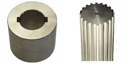
Passfedernut und Keilwelle erstellt mit Stoßtechnik
Keyway and Spline Profiles made with Broaching on CNC

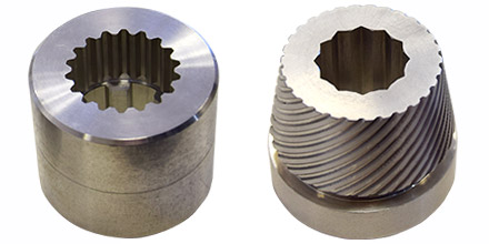
Kerbverzahnung und Spiral erstellt auf CNC-Drehmaschine
Spline and Spiral profiles made on a CNC Lathe

Broaching operations can be done on CNC milling and lathes as well as on broaching machines, whereby most CNC applications occur on lathes, since the workpiece can be finished without re-clamping. The C-axis is required for polygon profiles such as square, hexagonal, serrations and splined shafts. To open a single keyway, only the Z and X axes are usually sufficient. It is important that the lathe’s chuck can be locked, as the chuck must remain fixed while the keyway is being machined.

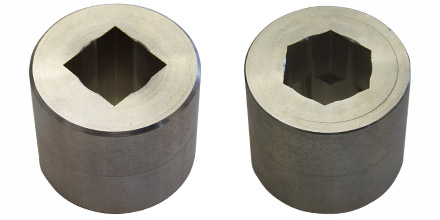
Innenvierkant und Innensechskant Profile erstellt mit Stoßverfahren
Square and Hexagon profiles made with broaching operation

Static and Live Broaching Tools

There are static as well as driven tool solutions. The right choice depends primarily on the number of keyways / edges / teeth and workpieces per month. With a smaller number of workpieces up to around a few thousand pieces per month, the static slotting tools are very cost-effective. However, if the number of pieces is over several thousand per month, a live broaching tool is faster and economically the better solution.

Statische Nutstoßwerkzeuge: Stoßplatten und Plattenhalter
Static slot cutting tools: inserts, insert holders and eccentric bushing for adjusting the Y-axis 

Static broaching solutions, which are widely used, consist of broaching (slotting) tools with a cylindrical clamping option and inserts in various geometries, sizes and tolerances. This technique has two components: the insert and the insert holder. The insert is attached to the insert holder with a screw. The insert holder, usually with a shaft diameter of 25 mm or 32 mm, is then clamped to a boring bar holder or a VDI boring bar holder with a corresponding diameter on the CNC lathe. For use on machining centers, the holder can be clamped with any tool holder with a cylindrical holder, such as a collet chuck or Weldon holder which you can easily supply from your local vendor.

By pushing the insert into the workpiece, the keyway is machined step by step. The cutting speed and the cutting depth must be set depending on the workpiece material. Experience shows here that catalog values mostly only serve as approximate values and that values adapted to various factors on site (room temperature, machine type, machine condition, workpiece quality, coolant, etc.) can produce optimal machining results.

Außenverzahnung mit Angetriebenes Stoßgerät auf CNC-Drehmaschine mit C-Achse.
External gear with live broaching tool on CNC lathe with C-axis.

The question that often arises here is whether broaching does not place too much stress on the turret or spindle of the CNC machine. The load that is exerted on the CNC lathe or machining center is comparable to that of a drilling operation. Larger sizes can be machined in two steps first using a smaller insert, then the actual size.

A Y-axis is not necessary for applications on lathes. However, if the lathe does not have a Y-axis, an eccentric bushing is necessary to correct the errors on the theoretical Y-axis of the turret. Over time, there is usually a play in the Y-axis on lathes and so that the grooves are exactly in the middle, this error must be corrected with an eccentric bushing. The C-axis is absolutely necessary for square, hexagonal and gear machining, as all edges or teeth are machined individually.

Comparison of static broaching tools vs live broaching tools:

Static Broaching Tool Live Broaching Tool
Speed
No Load on the turret
Efficient with higher quantities
Efficient with lower quantities
Usage without C-Axis
Machining length over 65mm
Usage on machining centers
Keyway, square, hexagon and spline profile machining

Live broaching tools are worthwhile for large quantities and provide the following advantages in the long term:

  • Cost-efficient production of different geometries
  • Resource-saving production and protection of the lathe turret
  • Low investment costs compared to purchasing a separate broaching machine
  • Fast processing. Up to 400-800 strokes per minute


Example application of the live broaching tool on a lathe with C-axis

Slot Broaching or Rotary Broaching?

For internal square, internal hexagon and internal gear machining, an alternative method is the rotary broaching process. Rotating broaching tools are relatively fast because the entire profile is machined at once and not all edges individually, as is the case with slot broaching.

Räumwerkzeug - Innensechskant
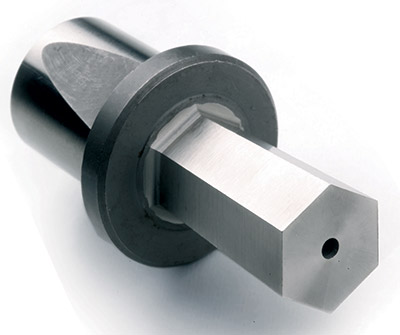
Rotary Broaching Tool – Hexagon Profile

Broaching tools can also be used flexibly on lathes and machining centers. Since processing only has to take place in one pass, the stress on the machine is very high. The machine can often come to a standstill, especially with larger diameters. Process reliability is therefore not guaranteed, especially with larger diameters and materials with higher hardness levels.

With broaching tools, machining can be done in as many passes as necessary. This guarantees process reliability, as the machining parameters can be adjusted depending on the material and profile size.

Comparison: Slot Broaching vs Rotary Broaching

Slot Broaching Rotary Broaching
Process reliability
Less load on the machine tool
Machining in multiple passes
Relatively lower price
Machining length over 70mm
Machining diameter over 20mm
High precision
Keyway profile
Square, Hexagon, Spline profile
Usage on CNC lathe and machining centers
Speed
Open Polygonal profiles without C-Axis

What should you consider when selecting inserts and insert holders?

There are no standard interfaces for inserts and insert holders. This is why vendors of broaching tools usually have a system with their own interfaces and the inserts are usually not interchangeable.

One of the most important technical points to consider when it comes to inserts is the material inserts are made of. Carbide is not suitable for broaching because its low breakage strength does not guarantee process reliability. You can make 100 keyways with a carbide insert, but the edges might break off after a few machining operations. In addition, the surface quality of your keyway might start deteriorating as early as after opening a dozen keyways.

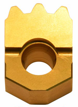
HSS Insert TIN-Coated – Spline Profile

In the manufacture of inserts, preference must be given to materials with high wear resistance and high compressive strength, e.g. powder metallurgical HSS alloys with resistant elements. Inserts made of suitable HSS alloys have a longer life due to the wear resistance and offer much greater process reliability thanks to the high pressure resistance.

With a TIN coating, the wear resistance and life of inserts can be increased. The geometry of the panels is also an important technical point that influences the surface quality, among other things. TiAlN coating may be prefered when machining harder materials.

Comparison: Sintered HSS-Alloy Insert vs Carbide Insert for Broaching

Sintered HSS-Alloy Carbide
Process Reliability
Wear Resistance
Pressure Resistance
Useful Life
Constant Surface Quality
Resharpening possibility
Relatively lower price

For the commercial aspects, particular attention should be paid to the size, tolerance and availability selection. If there are several common tolerances to choose from and are available as catalog goods, the procurement costs are lower in contrast to special plates on request. When machining keyways, tolerances H7, JS9, P6 and C11 are the most common.

Nutenstoßwerkzeug - Plattenhalter
Slotting Tool – Insert Holder

With insert holders, stability is of the utmost importance, as better stability for a longer service life of the inserts and better surface quality. With the holder, a longer shaft contributes to the stability, with a larger contact surface and, if necessary, fastening with two screws instead of one screw. A continuous substructure behind the insert seat ensures vibration damping and thus also increases the stability of the holder. Short insert seat protection must be avoided for optimal surface and service life of the insert.

Coolant supply through the holder ensures removal of the chips, a better surface and protection of the cutting edge.